Pneumatic actuators ПЗ
Pneumatic actuators ПЗН
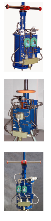
Special types of pneumatic actuators ПЗ
Pneumatic actuators ПЗ without the manual alternate
Pneumatic actuators ПЗ with the offset control panels and Example of record by ordering
|
Application Pneumatic actuators are meant for installation to wedge valves with a live spindle as well as for controlling the process of opening and closing the valves in the remote and local modes. In the distant mode the control is made through the injection of pneumatic and electrical signals to the pneumatic actuator, in the local mode – with the help of control bodies, being on the pneumatic actuator. The pneumatic actuator provides the injection of information signals (pneumatic and electric) about the position of the valve (“OPEN” or “CLOSED”). ü Recommended producers of wedge valves: ¨ OJSC “Tyazhpromarmatura”, Aleksin, Tulskaya oblast; ¨ OJSC “IKAR” Kurganskiy zavod truboprovodnoy armatury, Kurgan; ¨ OJSC “Penztyazhpromarmatura”, Penza; ¨ LLC “Yugo-Kamskiy mashinostroitelny zavod”, p. Yugo-Kamskiy Permskoy oblasti; ¨ OJSC “Blagoveshenskiy armaturniy zavod”, Blagoveshensk, Republic of Bashkortostan; ¨ CJSC “ARMAGUS”, Gus-Hrustalniy Vladimirskoy oblasti; ¨ CJSC “GUSAR”, Gus-Hrustalniy Vladimirskoy oblasti; ¨ OJSC “ARMZ”, Angarsk Irkutskoy oblasti; ¨ Valves of other manufacturers – by separate order. ü Port area of the valves: DN50, … , DN600. ü Conventional pressure of the valves: PN3, … , PN250. ü Pneumatic actuators can be installed and operated in explosion hazardous areas of grades 1 and 2 according to GOST Р 51330.13-99 (МЭК 60079-14-96), also to “The rules electric installations’ arrangement” (ПУЭ) Chapter 7.3 and other directive documents, governing the application of electric equipment in explosion hazardous areas.
Characteristics Pneumatic actuators ПЗ are made for providing the following operation modes of the valves (agreed by order): – closing the valve at the speed from 3 up to 5 mm/s; – increased operation speed (opening and closing time of the valve doesn’t exceed 12 s); – controlled process of opening and closing of the valve (according to the law of the control signal change). Pneumatic actuators are installed on the valves, made in the performance “with electric drive” and “with manual drive” (agreed by order). Pneumatic actuators ПЗН are made for providing the following operation mode of the valves: – increased operation speed (opening and closing time of the valve doesn’t exceed 12 s). |
 |
Conventional designation of pneumatic actuators
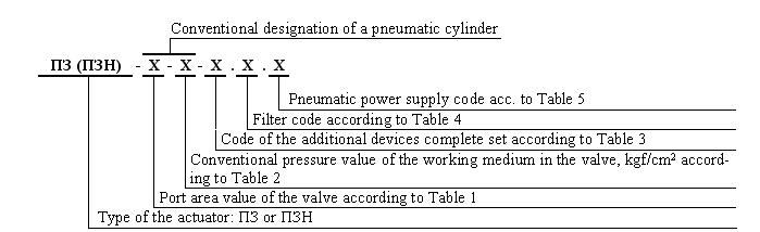
Type of the actuator:
- Pneumatic actuator ПЗ – is applied for joint operation with the valves, installed on technological pipelines if installations, and it provides opening and closing of the valves by the commands of the operator or ATPCS (automated technological processes control system).
- Pneumatic actuator ПЗН – is applied for joint operation with the valves, installed on loading racks, and it provides forced closing of the valve by the fill-up of the reservoir.
Table 1
|
Port area value of the valve |
50 |
80 |
100 |
150 |
200 |
250 |
300 |
350 |
400 |
500 |
600 |
|
Port area of the valve |
DN50 |
DN80 |
DN100 |
DN150 |
DN200 |
DN250 |
DN300 |
DN350 |
DN400 |
DN500 |
DN600 |
Table 2
|
Conventional pressure value of the working medium in the valve, kgf/cm2 |
3 |
10 |
16 |
25 |
40 |
63 |
160 |
250 |
|
Conventional pressure of the working medium in the valve |
PN3 |
PN10 |
PN16 |
PN25 |
PN40 |
PN63 |
PN160 |
PN250 |
Table 3
|
Code of the additional devices complete set |
Contents of the additional devices complete set |
|
00 |
Pneumatic air distributor with two control inputs. |
|
Two pneumatic limit switches. |
|
|
01 |
Pneumatic air distributor with one control input. |
|
Two pneumatic limit switches. |
|
|
Filling pickup. |
|
|
02 |
Pneumatic air distributor with two control inputs. |
Two spark-proof inductive limit switches. |
|
|
03 |
Two spark-proof electro pneumatic distributors with one output. |
Two spark-proof inductive limit switches. |
|
|
04 |
Two explosion-protected electro pneumatic distributors with one output. |
|
Two explosion-protected electric limit switches. |
|
|
05 |
One explosion-protected electro pneumatic distributor with two outputs. |
|
Two explosion-protected electric limit switches. |
|
|
Initial condition of the pneumatic actuator (by the absence of the control signal) – normally-closed (NC). |
|
|
06 |
One explosion-protected electro pneumatic distributor with two outputs. |
|
Two explosion-protected electric limit switches. |
|
|
Initial condition of the pneumatic actuator (by the absence of the control signal) – normally-open (NO) |
|
|
07 |
One spark-proof electro pneumatic distributor with two outputs. |
|
Two spark-proof inductive limit switches. |
|
|
Initial condition of the pneumatic actuator (by the absence of the control signal) – normally-closed (NC). |
|
|
08 |
One spark-proof electro pneumatic distributor with two outputs. |
|
Two spark-proof inductive limit switches. |
|
|
Initial condition of the pneumatic actuator (by the absence of the control signal) – normally-open (NO). |
|
|
09 |
Electro pneumatic spark-proof positioner. |
Two spark-proof inductive limit switches. |
|
|
10 |
Electro pneumatic spark-proof positioner. |
|
Two explosion-protected electric limit switches. |
|
|
11 |
Two explosion-protected electro pneumatic distributors with one output. |
Two spark-proof inductive limit switches. |
|
|
12 |
Two spark-proof electro pneumatic distributors with one output. |
|
Two explosion-protected electric limit switches. |
Table 4
Filter code |
Performance variant |
|
0 |
Filter absent |
|
1 |
Air pressure filter-stabilizer |
Table 5
Code of the pneumatic power supply |
Code of the additional devices complete set |
Pneumatic power supply (compressed air according to GOST 17433-80) with the pressure: |
||
Power circuit supply |
Power supply of the pneumatic control circuits |
|||
for actuators without the air pressure filter-stabilizer(filter code 0) |
for actuators with the air pressure filter-stabilizer(filter code 1) |
|||
|
0 |
00 and 01 |
1 (0,40 ± 0,04) MPa grade 0, 1, or 3 |
– |
(0,140 ± 0,014) MPa grade 0, 1 or 3 |
|
02 |
1 from 0,60 up to 0,80 MPa grade 3 or 5 |
|||
|
03, 04, 05, 06, 07 and 08 |
1 (0,40 ± 0,04) MPa grade 0, 1, or 3; 2 (0,140 ± 0,014) MPa grade 0, 1 or 3 |
1 (0,40 ± 0,04) MPa grade 0, 1, or 3; 2 from 0,60 up to 0,80 MPa grade 3 or 5 |
– |
|
|
1 |
02 |
1 (0,40 ± 0,04) MPa {for pneumatic cylinders 500‑10 and 600‑10 – (0,60 ± 0,06) MPa } grade 0, 1, or 3 |
1 from 0,60 up to 0,80 MPa (for pneumatic cylinders 500‑10 and 600‑10 – from 0,80 up to 1,00 MPa) grade 3 or 5 |
(0,40 ± 0,04) MPa { for pneumatic cylinders 500‑10 and 600–10 – (0,60 ± 0,06) MPa } grade 0, 1, or 3 |
|
03, 04, 05, 06, 07 и 08 |
– |
|||
Recommended types of the applied additional devices:
- Spark-proof inductive limit switch – inductive sensor Bi5‑G18‑Y1X/S97 of the firm “TURCK GmbH&Co.KG”, Germany, (can be supplied with the spark-explosion-protected switching amplifier IM1-22EX-R).
- Explosion-protected electric limit switch – explosion-protected switch ВВ‑2‑01 5Д3.609.005 ТУ.
- Spark proof electro pneumatic distributor with one output – spark-proof distributing solenoid valve WPISXB314A300 of the firm “ASCO”.
- Spark-proof electro pneumatic distributor with two outputs – -proof distributing solenoid valve WPISXB551A319 of the firm “ASCO”.
- Explosion-protected electro pneumatic distributor with one output – two-position explosion-protected distributor РДВ-2А ТУ6-90 5Д2.954.021 ТУ.
- Explosion-protected electro pneumatic distributor with one output – solenoid valve NFXG327FD11 24VDC of the firm “ASCO”.
- Explosion-protected electro pneumatic distributor with two outputs – two-position explosion-protected distributor РДВ-4 ТУ6-90 5Д2.954.022 ТУ.
- Electro pneumatic spark-proof positioner – electric pneumatic positioner ЭПП‑Ех-2 4-20 mA 400 kPa (600 kPa) 4 У1 ТУ 311‑0227471.030-93.
- Air-pressure filter-stabilizer – ФСДВ-10-У1 ЦТКА.408862.001 ТУ.
A T T E N T I O N:
ON CUSTOMER’S DEMAND THE TYPE OF THE APPLIED DEVICES CAN BE DIFFERENT, HAVING ANALOGOUS CHARACTERISTICS WITH THE RECOMMENDED ONES, WHICH IS TO BE AGREED BY ORDER.
For example, instead of the explosion-protected switch ВВ-2-01 5Д3.609.005 ТУ –there can be the explosion-protected switch ВВ -3-04 5Д3.609.007 ТУ installed.