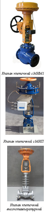
The valves for the working medium temperature from – 40 °C up to + 225 °C inc
The valves for the working medium temperature from – 40 °C up to + 400 °C inc
Basic technical data of the control cellular valves
|
Application The control cellular valves are stationary elements of automated control systems for technological processes and they are meant for controlling the flow discharge of the working medium in automated control systems for technological processes. The operation principle of the valves is based on the change of hydraulic resistance due to the change of the flow area of the control body by the movement of the closure plunger (slide). By the change of the hydraulic resistance there appears the change of the discharge capacity of the valves. The slide movement in the valves is made with the help of the executive mechanism, the shaft of which is rigidly attached to the closure plunger.
Characteristics Control cellular valves with the straightway body, balanced, with the flanged connection to the pipeline, with the pneumatic (PM), electrical (EM) or manual (MM) executive mechanism (drive). Rod seal – gland seal. Types of executive mechanisms: – pneumatic: pneumatic membrane-spring executive mechanism MEM1, pneumatic piston executive mechanism МИП; – electrical: electrical forward trace executive mechanism. Action type of the valves with the pneumatic drive: – normally-open (NO); – normally-closed (NC). The type of the discharge characteristic: – linear (L); – equal-percentage (E). The type of gasket in the closure: – “metal on metal” (MM); – “metal on elastomer” (ME); – “metal ceramic” (MC). Leak-proofness grade in the valve closure: – II according to GOST 23866-87 (the admissible leakage in the closure doesn’t exceed 0,5 % of Кvу), – III according to GOST 23866-87 (the admissible leakage in the closure doesn’t exceed 0,1 % of Кvу), – IV according to GOST 23866-87 (the admissible leakage in the closure doesn’t exceed 0,01 % of Кvу), – А or В according to GOST 9544-2005. The type of the climatic performance of the valves: – У1 according to GOST 15150-69, but for operation under temperature from minus 50 °C up to plus 50 °С. – ХЛ1 according to GOST 15150-69. The sound level, created by the valves, doesn’t exceed 80 dB·A. The valves can be equipped with additional units: a manual alternate, a pneumatic or electric pneumatic positioner, electro-pneumatic valve, limit switches, stabilizer-filter. By the customer’s order the valves can be supplied with the cooling (heating) jacket of the control body. |
 |
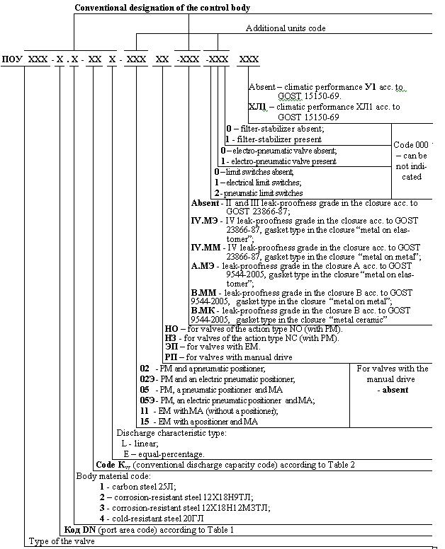
Conventional designation of valves
The material of the basic parts, which directly touch the medium controlled, correspond to the material of the body, excluding the products with the bodies from carbon steel, in which the closure parts are made of steel 12Х18Н9(10)Т.
Table 1
|
Code DN |
1 |
2 |
3 |
4 |
5 |
6 |
7 |
8 |
9 |
10 |
11 |
|
Port area |
DN 25 |
DN 50 |
DN 80 |
DN 100 |
DN 150 |
DN 200 |
DN32 |
DN40 |
DN65 |
DN125 |
DN250 |
Table 2
|
Code Кvу |
01 |
02 |
03 |
04 |
05 |
06 |
07 |
08 |
09 |
10 |
|
Conventional discharge capacity Кvу, m3/h |
2,5 |
4,0 |
6,3 |
10,0 |
16,0 |
25,0 |
32,0 |
40,0 |
63,0 |
80,0 |
|
Code Кvу |
11 |
12 |
13 |
14 |
15 |
16 |
17 |
18 |
19 |
20 |
|
Conventional discharge capacity Кvу, m3/h |
100,0 |
125,0 |
160,0 |
250,0 |
320,0 |
400,0 |
500,0 |
630,0 |
830,0 |
1000,0 |
The correlation of the code Кvу (Кvу) and the port area of the produced valves is given in Table 3.
Table 3
|
Code Кvу |
01 |
02 |
03 |
04 |
05 |
06 |
07 |
08 |
09 |
10 |
11 |
12 |
13 |
14 |
15 |
16 |
17 |
18 |
19 |
20 |
|
|
Кvу, m3/h |
2,5 |
4,0 |
6,3 |
10,0 |
16,0 |
25,0 |
32,0 |
40,0 |
63,0 |
80,0 |
100,0 |
125,0 |
160,0 |
250,0 |
320,0 |
400,0 |
500,0 |
630,0 |
830,0 |
1000,0 |
|
|
Port area |
DN25 (code 1) |
Л,Р |
Л,Р |
Л,Р |
Л,Р |
|
|
|
|
|
|
|
|
|
|
|
|
|
|
|
|
|
DN32 (code 7) |
|
|
|
Л,Р |
Л,Р |
|
|
|
|
|
|
|
|
|
|
|
|
|
|
|
|
|
DN40 (code 8) |
|
|
|
Л,Р |
Л,Р |
Л,Р |
|
|
|
|
|
|
|
|
|
|
|
|
|
|
|
|
DN50 (code 2) |
|
|
|
|
Л,Р |
Л,Р |
Л,Р |
Л,Р |
|
|
|
|
|
|
|
|
|
|
|
|
|
|
DN65 (code 9) |
|
|
|
|
|
Л,Р |
Л,Р |
Л,Р |
Л |
|
|
|
|
|
|
|
|
|
|
|
|
|
DN80 (code 3) |
|
|
|
|
|
|
|
|
Л,Р |
Л,Р |
Л,Р |
|
|
|
|
|
|
|
|
|
|
|
DN100 (code 4) |
|
|
|
|
|
|
|
|
|
|
Л,Р |
Л,Р |
Л,Р |
|
|
|
|
|
|
|
|
|
DN125 (code 10) |
|
|
|
|
|
|
|
|
|
|
Л,Р |
Л,Р |
Л,Р |
Л |
|
|
|
|
|
|
|
|
DN150 (code 5) |
|
|
|
|
|
|
|
|
|
|
|
|
Л,Р |
Л,Р |
Л,Р |
Л,Р |
|
|
|
|
|
|
DN200 (code 6) |
|
|
|
|
|
|
|
|
|
|
|
|
|
Л,Р |
Л,Р |
Л,Р |
Л,Р |
Л |
|
|
|
|
DN250 (code 11) |
|
|
|
|
|
|
|
|
|
|
|
|
|
|
|
|
Л,Р |
Л,Р |
Л,Р |
Л |
|
|
Notes: 1. The sign “Л;Л,Р” means the admissible combination of the conventional discharge capacity and the port area. 2. Л – linear discharge characteristic, Р – equal-percentage. |
|||||||||||||||||||||
Recommended types of the additional units applied are given in Table 4.
Table 4
|
Additional units or devices |
Recommended types |
|
|
Manual alternate |
Side manual alternate (SMA), top manual alternate (TMA) |
|
|
Pneumatic positioner |
OJSC “Saranskiy priborostroiteliy zavod”, the firms “Samson”, “Siemens”, “smC” |
|
|
Electric pneumatic positioner |
OJSC “Saranskiy priborostroiteliy zavod”, the firms “Samson”, “Siemens”, “smC” |
|
|
Pneumatic limit switch |
Pneumatic limit switch ВКП 6-1 ЗИ3.602.004 ТУ 51-924-80 |
|
|
Electrical limit switch |
Explosion-protected switch of OJSC “Avtomatika” Voronezh, CJSC NPP “SElHA” Voronezh, inductive noncontact sensor of the firm “TURCK”, limit position alarm of the firm “SAMSON” |
|
|
Electro-pneumatic valve |
Two-position explosion-protected dispatcher of OJSC “Avtomatika” Voronezh, CJSC NPP “SElHA” Voronezh, solenoid valve of the firm “ASCO” |
|
|
Filter-stabilizer |
Air pressure filter-stabilizer of OJSC “Saranskiy priborostroiteliy zavod”, the firms “CAMOZZI”, “SMC” |
|
|
Explosion-protected EM with MA (without a positioner) |
“ZEiM” Cheboksary, “ChEAZ” Cheboksary, “Tulaelectroprivod” |
|
|
Explosion-protected EM with a positioner and MA |
The firms “AUMA”, “ROTORK”, LLC NPO “Tomskaya electronnaya companiya” |
|
A T T E N T I O N:
THE TYPE OF APPLIED ADDITIONAL UNITS IS AGREED BY ORDER.
The electrical devices (positioners, EM, limit switches, electro-pneumatic valves), applied in the valves, have explosion-protected performance.
The mounting flanges are produced according to GOST 12819-80 with the seal faces and connecting dimensions according to GOST 12815-80, performance 5 (slot flanges).
Return (mounting) flanges are produced according to GOST 12821-80, performance 4, and together with attachment and seal parts are included into the complete set of mounting parts.
Operating position of the valves:
– any (preferably executive mechanism up) for ПОУ32Р, ПОУ32/1Р, ПОУ32/2Р and ПОУ33Р (except DN200 and DN250);
– vertical (executive mechanism up) for ПОУ51Р, ПОУ51/1Р, ПОУ51/2Р, ПОУ52Р and all types with DN200 and DN250.